
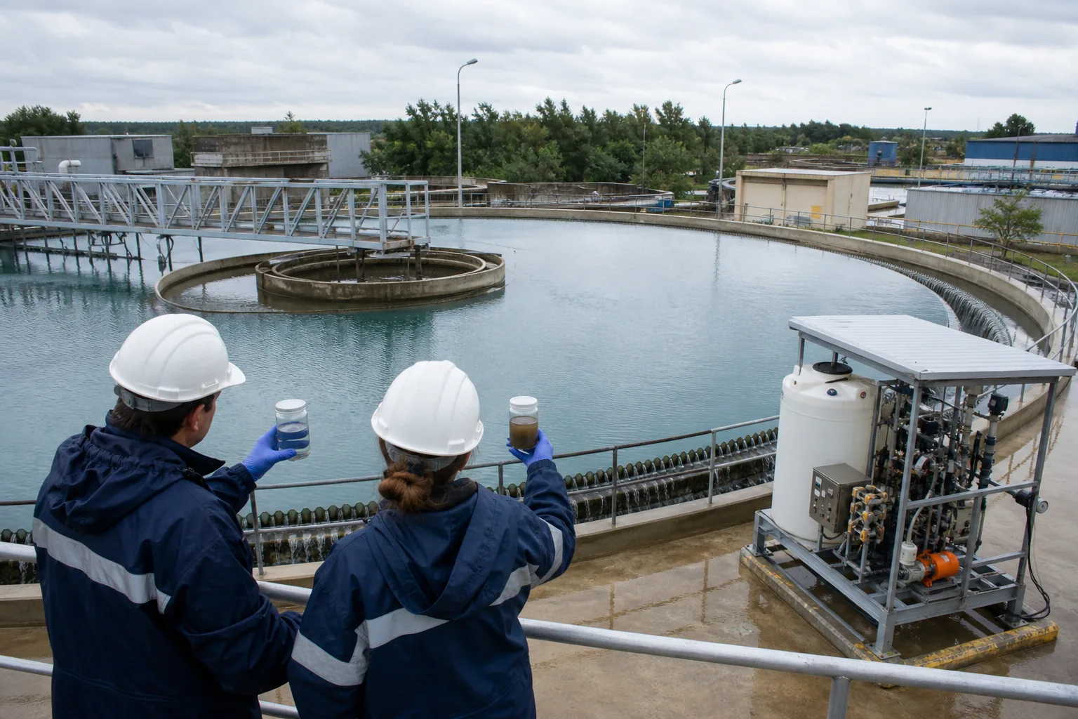
Recognize different separation forces
Gravity clarifiers depend on a density difference and a floc that settles at the applied hydraulic load. DAF depends on bubble attachment and a float layer that can be removed without releasing solids. A polymer selected for one route may not provide the same balance in the other.
Define whether the target is settled sludge, floated solids, filter protection or recycle-water quality before testing.
Map upstream destabilization
Metal salts, pH correction, emulsion breaking and rapid mixing determine the surface presented to the flocculant. Record addition order and the delay between chemicals. A secondary polymer cannot be interpreted without this upstream condition.
Use the actual water and feed, including recycle streams, oils or surfactants that affect bubbles and adsorption.
Use clarifier endpoints
Measure settling interface, overflow turbidity or suspended solids, compacted volume and sludge withdrawal behavior. Include a controlled shear step when floc passes through pumps or a feedwell. Observe the full residence delay during plant changes.
A very fast but open floc can settle initially yet build a bulky bed. Retain rate and compaction together.
Use DAF endpoints
Measure clarified effluent, float blanket formation, skimmability, recycle pressure and sludge solids. Polymer timing relative to air release matters; excessive shear after bubble attachment can change capture.
Avoid selecting solely from a settling jar. Use a flotation simulation or plant trial that represents the actual recycle and contact sequence.
Compare delivered process value
Normalize dose on active product and stable feed basis, then include coagulant demand, sludge volume, energy, throughput and downstream filter load. Product price alone does not reveal the better separator choice.
Request samples with separator design, flow, feed analysis, current treatment and acceptance endpoints attached.
Account for sludge return and recycle streams
Clarifier sludge return can change feed solids and surface condition, while DAF pressurized recycle changes collision and bubble attachment. Polymer trials should keep these recycle ratios stable or record them as deliberate variables. A change in recycle can shift the apparent dose without any change in raw-water demand.
Sample the combined feed at the actual chemical-contact point and connect outlet results to the correct hydraulic delay. Avoid using one grab sample to represent a variable recycle loop.
Plan the conversion between separators
When a process considers moving from settling to flotation, retain the same feed characterization and product candidates but rebuild the contact and endpoint program. A DAF screen needs air-to-solids context, recycle pressure, bubble contact and float removal; a clarifier screen needs settling flux, overflow, compaction and withdrawal behavior.
Use side-by-side delivered-cost calculations that include sludge volume, downstream filtration and energy. Do not carry a jar-test winner directly from one separator into the other.
Verify the outlet with consistent sampling
Clarifier and DAF outlets can cycle with scraper movement, skimming, recycle changes and hydraulic peaks. Use fixed sampling points and times, or a defined composite, so one clean grab does not decide the trial. Record the separator surface and sludge-removal condition with each sample.
Compare turbidity or suspended solids using the same method and hold samples consistently before measurement. Connect every outlet value to the corresponding feed and dose after the known process delay.